Photomontages for LVIA and TVIA
Many Landscape or Townscape and Visual Impact Assessments (LVIAs / TVIAs) require photomontages as supporting material. This post introduces what is involved.
Overview of photomontages for LVIA
Photomontages illustrate the location, size, degree of visibility or appearance of a proposed development. There are various techniques which can be used to produce them.
Firstly, high-quality photographs are required. These need to be taken carefully using professional equipment. There is more information on LVIA photography in this blog post.
For LVIA work, photomontages are often verified by a viewpoint survey, which records the location of the camera and fixed reference points in the view to a high degree of accuracy. The survey data is used in CAD or 3d modelling software, which also contains a 3d model of the proposal.
In the 3d software (CAD, 3d Studio Max, Rhinoceros or similar), a virtual camera is created at the surveyed camera location. This virtual camera is calibrated to have the same parameters as the DSLR used to take the viewpoint photograph. By aligning the surveyed reference points with those on the viewpoint photo, a highly accurate photomontage can be produced. These are often referred to as accurate visual representations (AVRs) or ‘verified views’.
Notably, the resulting photomontage would be reproducible by another specialist using the same data and method. This means that the images can be considered reliable. In any project which may be placed under scrutiny due to its impact on landscape and views, this can be very worthwhile. It is of course worth noting however that any image will only be as reliable as the data and method which is used to create it.
Types of Accurate Visual Representation
The most basic AVRs (AVR level 0 or 1) show the location and massing of a proposed development as a simple outline (often referred to as a ‘wireline’). The most elaborate AVRs (AVR level 3) demonstrate how a development would appear in context and under the lighting and weather conditions of the back-plate photograph.
The London View Management Framework (Mayor of London, 2012) uses the following classification for types of AVRs.
AVR type |
Description |
| AVR level 0 | Location and size of proposal |
| AVR level 1 | Location, size and degree of visibility of proposal |
| AVR level 2 | As level 1 + description of architectural form |
| AVR level 3 | As level 2 + use of materials |
The choice of what level of AVR to produce depends on its end-purpose and practical aspects, including budget. Images showing detailed architecture and landscaping can be very time-consuming to produce.
Examples of Accurate Visual Representations
The image below is an AVR 1 for a commercial development in Newhaven, East Sussex.
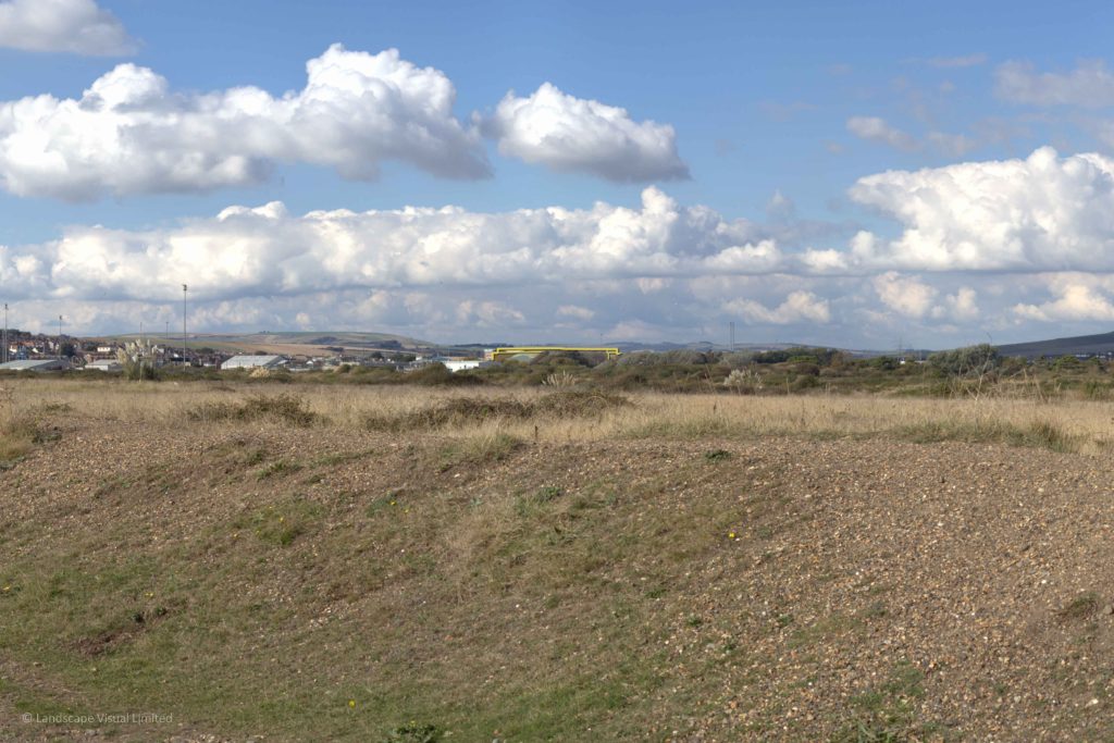
An example of an AVR level 1: a commercial development in Newhaven, East Sussex, shown as a yellow wireline
The images below show a viewpoint at Wild Park, in the South Downs National Park, on the edge of Coldean, Brighton and Hove. The first image is an AVR 2, which shows an architectural model ‘block-rendered’ in a neutral colour. The second image is an AVR 3, and shows materials and colour. More sophisticated rendering techniques and lighting and environment settings were used in producing the AVR 3.

An example of an AVR level 2 (block-rendered in a neutral colour): Coldean from Wild Park in the South Downs National Park
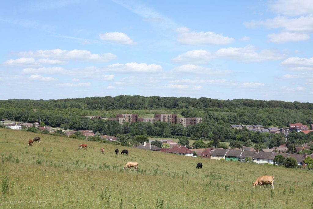
The same viewpoint as above to AVR level 3, showing architectural detail and materials
Guidance for photomontages
There is various guidance which is relevant to the preparation of photomontages:
- The Guidelines for Landscape and Visual Impact Assessment (‘GLVIA3’) (Landscape Institute and Institute of Environmental Management and Assessment, 2013) introduces a range of techniques and how they may be used in LVIA work.
- Landscape Institute Technical Guidance Note 06/19 Visual Representation of Development Proposals was published in September 2019 and amplifies the broad principles introduced in GLVIA3.
Sector or local guidance sometimes stipulates the requirements for material submitted with planning applications. Examples include:
- Visual Representation of Wind Farms (Scottish Natural Heritage, 2017).
- London View Management Framework supplementary planning guidance (London Plan 2011 Implementation Framework) (Mayor of London, March 2012).
The following image illustrates part of the output required by SNH’s wind farm guidance.
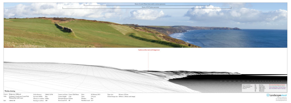
Baseline panorama and matched wireline as required by Scottish Natural Heritage’s Visual representation of wind farm guidance (cylindrical projection, image size 820mm by 130mm)
Summary
Photomontages often play an important role in landscape and townscape assessment. There is various guidance for producing photomontages for LVIA. However, none of this guidance details the exact methods or techniques to be used in actually producing the images. There are many different approaches and techniques which can be used, the approach normally being tailored to the project type and context. The production of photomontages can require the input of various specialists, including experienced photographers, surveyors and 3d-visualisers. Landscape Visual can produce high-quality photomontages as an integrated part of our LVIA / TVIA work.
If you would like to find out more about how we could help with your project, or if you would just like to find out more about any aspect of landscape planning, please get in touch.